Intergrowth Family MFI--ION
1-dimensional disorder of the connecting units
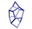
Periodic Building Unit
| Periodic Building Unit (PerBU): | Pentasil i layer | |||||
| Layer symmetry | P -1 | |||||
| 2D cell parameters | a = 20.09 Å | b = 13.14 Å | gamma = 90° | |||
| Comment | Adjacent pentasil chains in the layer are related by inversion centers | |||||
Connector
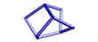
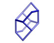
| Unit | -ION chain | 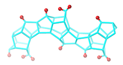 |
||
Connectivity pattern
| Examples |
 |
The layers are stacked along the [001] direction using the following connectivity patterns
| |||||||||||||||||
|
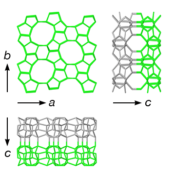
* relative to the previous layer Alternative description The intergrowth structure can be viewed as a stacking of 4 different layers: 1 Pentasil i layer (green) 2 mirror image of the Pentasil i layer (light green) 3 layer of -ION chains (blue) 4 inverted layer of -ION chains (dark blue) The rules for stacking are that: 1 can only be followed by 2 or 3 2 can only be followed by 1 or 4 3 can only be followed by 2 4 can only be followed by 1 The stacking 1 2 1 2 1 2 is that of polymorph MFI. The stacking 1 3 2 4 1 3 2 4 is that of polymorph -ION. |
| Effect on channel system | |
| The presence of connectors creates a dumbbell-shaped 16-ring opening to the sinusoidal channel along the [100] direction. Without the connectors, this is a round 10-ring opening. | |
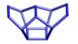
Simplest ordered end members
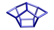
Connectors are shown in blue. The different shades indicate that that they are not identical, but related to one another by an inversion center.
Adjacent PerBUs generated by the same connectivity pattern (with or without connectors in between) are shown with different shades of the same color for clarity.
Adjacent PerBUs generated by the same connectivity pattern (with or without connectors in between) are shown with different shades of the same color for clarity.
| Polymorph MFI | |||||
| Cell Parameters: | orthorhombic | P n m a: (# 62) | |||
| a = 20.0900 Å | b = 19.7380 Å | c = 13.1420 Å | |||
| α = 90.000° | β = 90.000° | γ = 90.000° | |||
| Volume = | 5211.3 Å3 | ||||
| Framework Density (FDSi): | 18.4 | ||||
| Ring sizes (# T atoms): | 10 6 5 4 | ||
| Channel dimensionality: | Topological (pore opening > 6-ring): 3-dimensional |
| Maximum diameter of a sphere: | |||||||
| that can be included | 6.36 Å | ||||||
| that can diffuse along | a: 4.7 Å | b: 4.46 Å | c: 4.46 Å | ||||
| additional volume data | |||||||
| Composite Building Units: |
 |  |  |  | |
mor (t-tes ) | cas | mfi (t-pen ) | mel |
| In this space group and setting, the PerBUs are stacked along [010] |
|||||
| Note: This polymorph corresponds to the ordered framework MFI | |
| Polymorph -ION | |||||
| Cell Parameters: | orthorhombic | P n m a: (# 62) | |||
| a = 20.0314 Å | b = 34.8780 Å | c = 13.2653 Å | |||
| α = 90.000° | β = 90.000° | γ = 90.000° | |||
| Volume = | 9391.2 Å3 | ||||
| Framework Density (FDSi): | 17.0 | ||||
| Ring sizes (# T atoms): | 16 10 6 5 4 | ||
| Channel dimensionality: | Topological (pore opening > 6-ring): 3-dimensional |
| Maximum diameter of a sphere: | |||||||
| that can be included | 6.75 Å | ||||||
| that can diffuse along | a: 4.93 Å | b: 4.52 Å | c: 4.52 Å | ||||
| additional volume data | |||||||
| Composite Building Units: |
| |  | | ||||||
mor (t-tes ) | cas | stf (t-nuh ) | mfi (t-pen ) | | |||||
mel |
| In this space group and setting, the PerBUs are stacked along [010] |
|||||
| Note: This polymorph corresponds to the ordered framework -ION | |
Disorder Example
| Simple example of a random stacking of MFI and -ION polymorphs | |
| The straight 10-ring channels along the stacking direction are not blocked by the random disorder. |