Intergrowth Family MTT-TON
1-dimensional stacking disorder
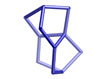
Periodic Building Unit
| Periodic Building Unit (PerBU): | TON layer | |||||
| Layer symmetry | p m 1 1 | |||||
| 2D cell parameters | a = 11.38 Å | b = 5.26 Å | gamma = 90° | |||
| References |
|||
| A. W. Burton, S. I. Zones, T. Rea, I. Y. Chan | |||
| "Preparation and characterization of SSZ-54: A family of MTT/TON intergrowth materials" | |||
| Microporous Mesoporous Mater., 132, 54 – 59 (2010) | |||
Connectivity pattern
| Examples |
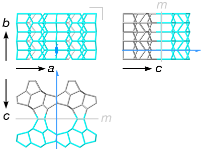 |
The layers are stacked along the [001] direction using the following connectivity patterns
| |||||||||||||
|
* relative to the previous layer Alternative description The relationship between the layers can also be described in terms of a mirror plane m (blue) or an inversion center i (purple), but there is no simple common PerBU for this description (it would require half-occupied T positions), so it has not been used. These symmetry operations are shown in gray in the images on the right. |
| Effect on channel system | |
| Disorder does not block the cannels | |
Simplest ordered end members
The color of each layer reflects the translation operation used to generate it from the previous layer (see Table above)
| Polymorph MTT | |||||
| Cell Parameters: | orthorhombic | P m m n:1 (# 59) | |||
| a = 5.2560 Å | b = 22.0310 Å | c = 11.3840 Å | |||
| α = 90.000° | β = 90.000° | γ = 90.000° | |||
| Volume = | 1318.2 Å3 | ||||
| Framework Density (FDSi): | 18.2 | ||||
| Ring sizes (# T atoms): | 10 6 5 | ||
| Channel dimensionality: | Topological (pore opening > 6-ring): 1-dimensional |
| Maximum diameter of a sphere: | |||||||
| that can be included | 6.19 Å | ||||||
| that can diffuse along | a: 5.07 Å | b: 2.2 Å | c: 1.53 Å | ||||
| additional volume data | |||||||
| Composite Building Units: |
 |  |  |  | |
jbw (t-hes ) | mtt | bik | ton |
| In this space group and setting, the PerBUs are stacked along [010] Adjacent layers generated by the same connectivity pattern (same basic color) are shown with different shades for clarity |
|||||
| Note: This polymorph corresponds to the ordered framework MTT | |
| Polymorph TON | |||||
| Cell Parameters: | orthorhombic | C m c m: (# 63) | |||
| a = 14.1050 Å | b = 17.8420 Å | c = 5.2560 Å | |||
| α = 90.000° | β = 90.000° | γ = 90.000° | |||
| Volume = | 1322.7 Å3 | ||||
| Framework Density (FDSi): | 18.1 | ||||
| Ring sizes (# T atoms): | 10 6 5 | ||
| Channel dimensionality: | Topological (pore opening > 6-ring): 1-dimensional |
| Maximum diameter of a sphere: | |||||||
| that can be included | 5.71 Å | ||||||
| that can diffuse along | a: 2.31 Å | b: 1.56 Å | c: 5.11 Å | ||||
| additional volume data | |||||||
| Composite Building Units: |
| | | | |
jbw (t-hes ) | mtt | bik | ton |
| In this space group and setting, the PerBUs are stacked along [110] Adjacent layers generated by the same connectivity pattern (same basic color) are shown with different shades for clarity |
|||||
| Note: This polymorph corresponds to the ordered framework TON | |
Disorder Example
| Simple example of a random stacking of MTT and TON polymorphs. | |
| There is no blocking of the 1D channel system. |